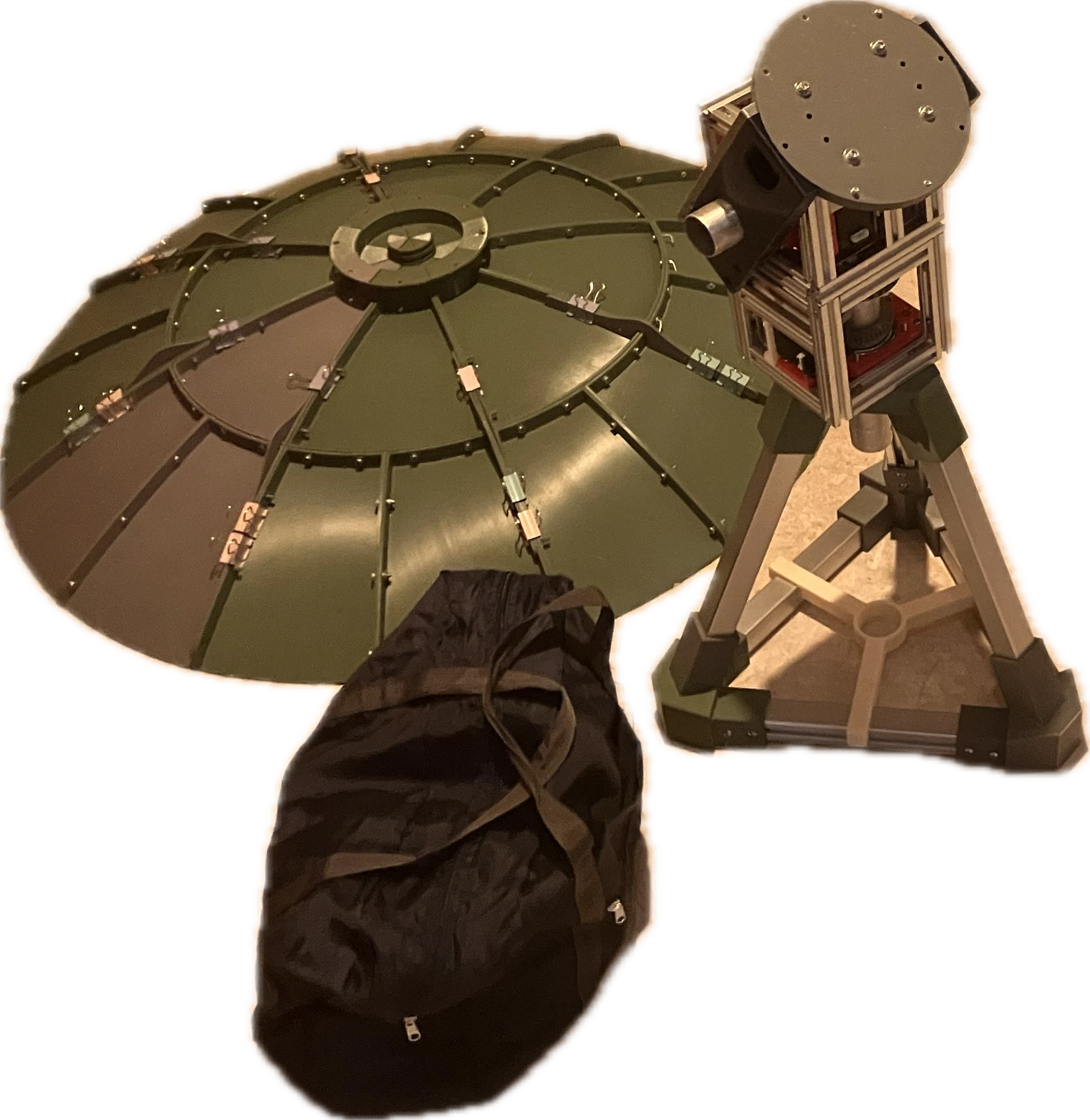
A one-metre, modular radio telescope built to make hands-on astronomy more accessible. Explore the design, the construction, and what the first field test taught us.
Eight replaceable dish segments, a pyramidal feedhorn, and a mount refined through repeated prototypes.
The one-metre reflectorAluminium tape forms the reflective surface over printed sections.Replaceable sectionsThe rear structure combines individual segments with supporting ribs.Before the reflective layerA single printed segment before surface finishing.The pyramidal feedhornPrinted reinforcing ribs help maintain the shape of the horn.Inside the feedAn aluminium-lined interior and copper pin form the receiving structure.Adjustable positioningThe feed position can be changed experimentally along three axes.
Azimuth and elevation control
The prototype adapts the SatNOGS Rotator v3 design. Credit to the SatNOGS contributors for the original rotator design. Two NEMA 17 stepper motors drive a belt-and-worm-gear system with a total reduction of 54:1.
The team replaced slipping set-screw connections with M8 bolts and refined the tripod through eight design iterations. Motorised pointing is a design capability, but the first field test encountered power and mechanical failures.
ASTRA 100 design specifications
Reflector
1 m diameter, eight sections
Focal ratio
f/D = 0.4
Printed material
ABS for main printed components
Feed
Pyramidal horn with adjustable mount
Rotator
Modified SatNOGS v3
Gear reduction
54:1, combined stages
Mount controller
Makerbase SBASE V1.3
Measured status
Single prototype; validation ongoing
The rotator assemblyTwo rotation modules position the dish.Iterating the tripodSix aluminium profiles support the printed connecting parts.Putting it togetherThe slides document revisions to the mount and component layout.
The details behind the build
Quick-assembly ribsRibs reduce the number of fasteners needed during assembly.Supporting the reflectorA close-up of the structure behind the dish.Bolted connectionsM8 bolts replaced slipping set-screw connections.A replaceable collarA separate collar accommodates fit without reprinting the larger part.Keeping the base alignedThe lower structure helps locate the aluminium profiles.A mounting challengeThe first test exposed the need for a more rigid connection.
Select a photograph to inspect it. Construction imagery comes from the supplied report and presentation.
02 / Electronics & software
From radio waves to data.
The receiving chain links the feed to an amplifier and filter, a software-defined radio, and a computer.
FeedhornCopper receiving pin
→
LNA + filterAmplify and select
→
SDRDigitise the signal
→
GNU RadioProcess and record
Amplifier and filterThe report specifies an integrated LNA and 1420 MHz bandpass filter.Mount electronicsThe combined controller and driver simplifies the rotator wiring.A revised installationLater slide photographs show a more integrated component layout.
Recording and calibration
The GNU Radio flowgraph transforms the incoming samples into power spectra and saves data in HDF5 files. Hot/cold calibration was attempted, but the report notes that the output remained in relative units and the calibration was not fully validated.
Controlling the mount
A Python interface sends GRBL G-code commands over USB serial to the SBASE controller. Calibration relates motor steps to the physical azimuth and elevation angles of the telescope.
GNU Radio signal processingOriginal PNG from the presentation, slide 30. Open full-resolution source image ↗The rotator control interfaceOriginal PNG from the written report, Annex 7. The source is 624 × 405 pixels; small labels have limited legibility. Open original source image ↗
Signal issue identified, corrective work in progress. The original FC0013-based receiver did not cover the 1420.4 MHz target. The project presentation records ordering an RTL-SDR V4. We’re addressing receiver compatibility and calibration before repeating the observations. Read the recovery plan ↓
03 / Field notebook
East Coast Park. 2 August, 23:00 – 3 August, 04:00.
The first field test demonstrated that the telescope could be transported, assembled, and used to collect spectra. It also exposed problems with motor power, mechanical rigidity, and calibration.
Assembly in the fieldThe prototype set up outside the workshop.The first observing sessionA single telescope at the test site.Learning on sitePower, mounting, and calibration all needed attention.
Demonstrated
Assembly and data acquisition
The team assembled the instrument in the field and obtained HDF5 recordings and plotted spectra.
Partially achieved
Mechanical stability
The dish, tripod, and feed survived, but the rotator system required improvements after gear and mounting failures.
Not detected
The neutral-hydrogen line
No statistically significant feature near 1420.4 MHz was confirmed in the first test. The peak at 1421 MHz was classified as an instrumental DC spike. Fixing the receiver and validating the signal chain is now a priority.
Next frontier
Interferometry
The next stage builds on ASTRA 100 with paired telescopes, synchronised recordings, and signal correlation.
Current development / In progress
We’re working on the signal issue.
The first test gave us a problem to solve and a clear next step.
The initial spectra did not confirm astronomical hydrogen. Our follow-up investigation identified a receiver that could not cover the intended frequency. We’re addressing that limitation and improving the measurement process so the next observations can be tested properly.
01 / RECEIVER
Correct the frequency coverage
Use a suitable receiver for the 1420.4 MHz band. The RTL-SDR V4 replacement was ordered in the documented project update.
02 / SIGNAL CHAIN
Check and calibrate the system
Verify the receiver, amplifier, filter, connections, and power, then improve the hot/cold calibration procedure.
03 / VALIDATION
Repeat the observations
Look for a repeatable feature that can be distinguished from instrumental spikes and local interference, and document the results.
Receiver and calibration work is ongoing, with repeat observations planned to validate the improvements and support the future network.
Raw spectrumOriginal figure from the written report, Annex 9. The central spike is instrumental, not a confirmed astronomical signal. Open original source image ↗After attempted calibrationOriginal screenshot from the presentation, slide 30 (also used on slide 32), at its full 2048 × 1330 resolution. The plots show System Temperature, Gain, and Signal. The source analysis did not confirm a hydrogen-line detection. Open full-resolution original ↗
Field lessons shape the next design.
The first worm-gear system failed under load. The report identifies brittle material, loose nuts, and inadequate mounting rigidity as issues. Other planned improvements include a feed counterweight and a simpler clip-on assembly mechanism.
Damaged PLA gearFirst field-test hardware.ABS gearAn alternative material documented in the report.
04 / Watch the project
The build, in motion.
The original project video, showing the build and later improvements.
Project improvements · original video from the presentation. Video supplied by the project team.
05 / Materials & cost
An accessible starting point.
The original tally totalled S$300.71, below the team’s S$400 target. It includes shipping and a miscellaneous allowance.
Selected entries from the prototype’s bill of materials
Component
Quantity used
Recorded cost (RMB)
ABS printing filament
7 kg
420.00
SBASE driver + controller
1
269.00
Original RTL-SDR V2
1
99.00
LNA + bandpass filter
1
60.00
NEMA 17 stepper motors
2
56.18
Aluminium tube
3 metres
60.00
30 × 30 mm aluminium profiles
6
52.26
Shipping
Entire order
200.00
Miscellaneous allowance
—
100.00
Full reported tally, including other parts
All components
1,582.96
Reported total: S$300.71
This is a selection, not the complete purchasing list. Prices and conversion are those in the report’s 3 August tally. The original SDR is documented for provenance; the slides identify it as unsuitable for the intended hydrogen-line frequency.
06 / Downloads
Technical report & materials.
Read the prototype’s technical record, or download the full component list separately.
PDF · 10 pages · 842 KB
Technical report
Design, construction, electronics, calibration, field-test findings, and the next development steps, with hardware photographs and source notes.
The bill of materials records the original prototype. Check the documented receiver limitation and unspecified entries before using it for a new build.
07 / Continue exploring
The working record.
The technical report brings together the design rationale, hardware photographs, calibration notes, and field-test analysis. The separate bill of materials preserves the complete original cost tally. Later receiver findings from the presentation are identified in both documents.
Where are the CAD files and assembly instructions?
The report describes a modular design. The ASTRA forum is a planned space for future build discussions and shared resources. No standalone CAD or firmware archive was included with these materials. The technical report and separate materials list are available above, and a future ASTRA design library can host versioned files when they are ready.
What needs to be improved before the next observation?
We’re actively addressing the signal issue, beginning with receiver compatibility and calibration. Reliable power, stronger rotator components, and feed counterbalancing remain part of the development plan. The next milestone is a repeatable astronomical detection. See the recovery plan ↓
Can multiple ASTRA telescopes work together today?
Interferometry remains a development goal. The report documents only one constructed node. Additional instruments, suitable timing and clocks, raw I/Q preservation, and correlation would need to be implemented and tested.
What comes from the report, and what comes from the slides?
The design, initial costs, field-test outcomes, and spectrum analysis come from the written report. The later SDR diagnosis, revised electronics photos, and main project video come from the presentation. Neither source establishes a successful hydrogen-line detection.
08 / Looking ahead
What’s next for ASTRA?
A more capable instrument, and a platform where builders can learn and observe together.
In progress
Reliable signal reception
Resolve the receiver issue, improve calibration, and repeat the observations. Publish the outcome so other builders can use what we learn.
Create accounts, post build journals and observations, ask questions, reply to other builders, and share files, modifications, and solutions.
Planned platform feature
Connect your telescope
Register an ASTRA station, describe its hardware and capabilities, and choose what to share. A station directory could help builders find collaborators and arrange joint observing sessions.
Experimental development
Interferometry connections
Start with two compatible telescopes. Develop precise timing, synchronised raw I/Q recordings, and correlation tools to test whether their signals can be combined into a shared observation.
The forum and connection tools are planned features. Interferometry also needs suitable hardware, stable clocks, and successful tests with multiple instruments. These capabilities are not live yet.